©2003-2012 W8JI
Revised 8/24/03
Revised May 18, 2005 R84 named in error R89 in harmonic adjustment
Major revision June 24, 2012
Warning!
Some MFJ manuals were re-written and distance-to-fault measurement procedure errors were introduced. I think this occurred sometime around 2002, but was later corrected. If your manual tells you to tune to the next band up or down when measuring any length process (stubs, DTF, etc.) it is absolutely incorrect. The correct procedure is to tune for lowest Z on the meter and lowest X on the digital display, set the reading as "1", and then locate the very next dip UP or DOWN in frequency and store it in "2". You can tune either up or down from the initial null spot, but the next dip must be the very next frequency up or down where meter Z is lowest and X on the digital display is as low as possible. I'm not sure if any other errors were introduced in the manual rewrite.Â
|
History: My amigo JB was the primary MFJ259B designer, and I helped with firmware algorithms and RF and analog hardware. This information is here because it is the correct way to calibrate the MFJ-259B analyzer. This work is all donated. K1BQT took an instruction set supplied by MFJ, originally developed by JB, and re-wrote it. I reviewed, modified, and edited that work. This page is the most current result. It is best that no one copy this, and start handing it out in mass. The only reason for this request is there must be a point of control of information, so it can be corrected or expanded as modifications, errors, or omissions show up. I am not aware of any other source that gives correct calibration procedures. It is important that the MFJ259B be calibrated by these steps, even if they sound complex. Without following these steps many special functions may not work correctly, even if the unit tests properly on calibration loads! |
Please, try to read the manual!
Impedance readings are least accurate
when near 1:1 SWR. When adjusting a normal antenna, lowest possible SWR is
always lowest reactance. There might be exceptions to this, but the would only
occur if antenna or load changes resistance (real part) much faster than
reactance. I doubt this will happen.
If you see 1:1 VSWR, the impedance
has to be 50 j0. Do not waste time trying to make the analyzer read R50 X0 if
SWR says 1.0:1 or some acceptable SWR number. Even a few bits of error, or a
very small stray voltage on the connector, will affect the algorithm that
determines reactance. The firmware was supposed to contain an algorithm
that weighs the VSWR with priority over Vs and Vz used to determine impedance.
As sometimes happens, there is no assurance everyone stayed on the same page. I
did not write the code, I only suggested changes to minimize error. SWR readings
should be used to smooth R and X readings around 1:1 SWR, but I do not have a
high level of confidence that guideline was followed. Â
The most common simple failures are dirty band switches, broken antenna connector pin connections (this is fairly new, caused by a manufacturing change in the circuit board), and voltage impressed on the antenna connector from the antenna or load (not just broadcast stations).
This is an inexpensive bridge directly coupled to the feedline.
There is no RF or dc isolation from the connector to the bridge. This makes the
bridge sensitive to dc, low frequency ac, and RF voltages on virtually any
frequency from dc to light.
TEST: Broadcast RFI, or even low
frequency AC or DC voltages on the cables will produce errors. The easiest way
to check for these errors is to put the analyzer in Frequency Counter mode and
carefully observe the SWR meter. If the SWR meter deflects at all in the
Frequency Counter mode, the analyzer is being biased from the antenna port by
something.
I do NOT suggest using a low pass or high pass. I suggest using the MFJ device specifically designed as a bandpass filter. The MFJ device, properly used, will not seriously affect other readings like low pass or high pass filters do from filter passband ripples and phase shift.
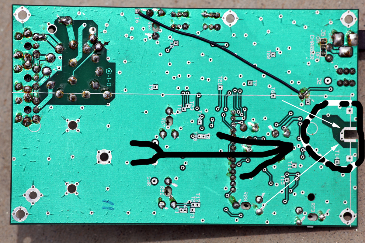
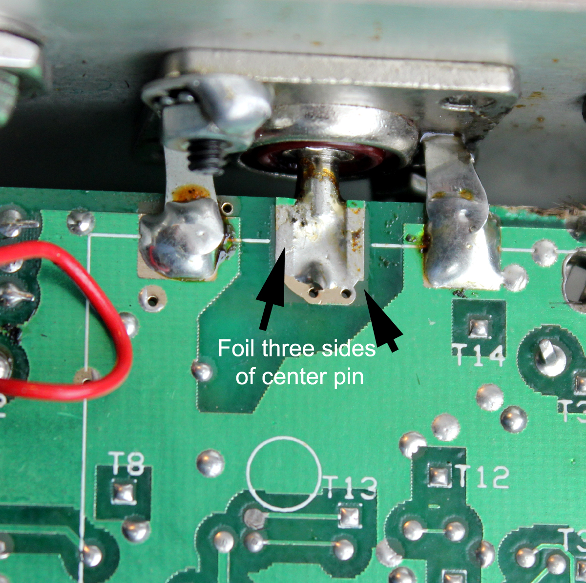
At some point after lead free solder was used, someone thinned down traces where the connector pin solders to the board. This was an idiotic mistake. Instead of just using a proper size and temperature iron to solder the pin with proper training, someone altered the board. While this allows solder to flow better, the traces are too weak to support the mechanical stress on the pin. There have been, off and on, attempts to use a jumper wire. That also was a really bad idea, the wire breaks.
This is the board area they changed. Thinning this trace down to improve soldering or using a solid wire is a serious mistake.
Good original board as engineered:
Correct pin soldering on good board:
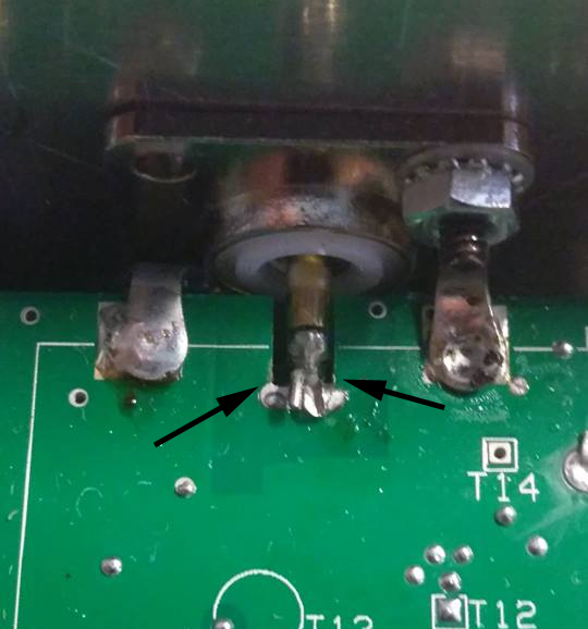
Revised defective pin area. Instead of teaching people to solder with correct tools, they thinned this trace. This ruins the connection life.
Another common issue is a dirty band switch. This shows specifically as a really jumpy frequency, even to the point the frequency reading goes way out of band or stops. This is a problem with switch grease and switch manufacturer quality control. The switch needs a little polishing and wetting of the contacts. Don't get all hyper about what cleaner to use. WD40 will work fine. Lay the analyzer on it's back, remove the switch knob, and spritz just a ting bit of normal WD40 on the shaft, allow it to run down into the shaft bushing. Run the switch back and forth rapidly. Do not soak the switch, but use enough to wet the switch internals and soften the internal grease.Â
Note: A dirty switch shows as unstable or major erratic frequency readings. Minor jumping or drift in low digits is normal.
This type of analyzer contains an RF oscillator, a very linear amplifier to increase power, and an internal resistor bridge in a modified Whetstone bridge configuration.
Since it is designed to be inexpensive and simple, and since the design is aging now, there are a few pitfalls with this system.Â
The bridge is dc-coupled from an internal resistor bridge to the antenna port. Each leg of the bridge has a diode detector. This is the weak point for accuracy.
The bridge detectors are NOT frequency selective, and respond to anything from minor dc offsets through microwave signals. This causes inaccuracies if any voltage over a few millivolts appears across the antenna port. (This is also true for competing analyzers from other manufacturers.)Â There are multiple reasons why, at the time of design, these units were dc coupled with broadband detectors. Hopefully someday a higher cost-design with selective detectors will become available, but for right now this is all that is available for amateur use from any manufacturer.'
The MFJ259 series RF power level is about 10 dBm, although this varies with the load impedance. Since the bridge depends on nulls, any external voltage will throw off readings.
The second shortfall is the internal amplifier must be linear and have very low total harmonic content. Total harmonic power, at the lowest load impedance, must be down at least 25dB and preferably 35dB. This is true for ANY antenna analyzer, since you do not want the analyzer to measure the load at two frequencies!Â
Because the detector is broadband and because it is dc coupled to the antenna, any external voltage across the antenna input port causes measurement errors. It is the accumulated voltage of multiple sources that is most important, not the strength of any individual signal. Because of that, large antennas should be tested at times when propagated signals in the range of the antenna's response are at minimum strength.Â
A definite RFI improvement occurs with a special parallel-tuned bandpass filter, but multiple-section bandpass, low pass, or high pass filters cause impedance measurement problems. Multiple-section filters behave like transmission lines of random line impedances, loss, and electrical length as frequency is varied. The best solution is to use a single-stage bandpass filter and dc isolation on large arrays or with long feed lines. I often use a good 1:1 isolation transformer for measurements, and often find a parallel L/C filter (like the MFJ-731 Filter) useful.
The bridge can be thought of as a simple voltage divider.
Voltage across Vz is R2/(50+R2) * 255 = bits
Voltage across Vs is 50/(R2+50) * 255 = bits
With 12.5 ohms R2 we have 12.5/50+12.5Â Â *Â Â Â 255 =Â 51 bits VzÂ
and 50/12.5+50Â Â * 255 = 204 bits Vs
Using this, it is possible to calibrate the 259B with higher values of load resistance. This may provide better high impedance accuracy.
This circuit is expanded to a bridge:
Other than manufacturing errors, the detector diodes clearly stand out as the most common problem. They are the most easily damaged devices in the analyzer. If you have a sudden problem, it is most likely a defective detector diode. Diode damage almost always comes from accidentally applying voltage on the antenna port.Â
Why are the diodes so sensitive?
In order for the detectors to be accurate within a fraction of a percent (one bit), detector diodes must have very low capacitance and very low threshold voltage. This means the diodes, through necessity, must be low-power zero-bias Schottky microwave detector diodes. The same characteristics that make them accurate and linear also cause the diodes to be especially sensitive to damage from small voltage spikes. ALWAYS discharge large antennas before connecting them to the analyzer! Never apply external voltages greater than 3 volts to the antenna port!
Measuring Stub and Fault Distance
I developed the distance to fault and stub length functions. The theory is frequency spacing between impedance minimums, when converted to half wavelengths, is the distance to an open or short. This requires the open or short be a reasonably good open or short, and not an antenna or load. This system works well, when applied properly. I successfully find opens and cuts in my trunk cables, some cables are 3000 feet long, within a few feet.  Â
For a short period of time, with the best of intentions, someone rewrote various manuals. Unfortunately, they arbitrarily changed manual instructions for stub length and distance-to-fault measurements. For a period of time, as a direct result of this error, MFJ support instructed customers to ignore the older, original, and correct manual. The new manual, now long out-of-print, advised tuning for the second impedance dip on the next band-range up or down from the first dip. This is absolutely wrong.
The original manual was correct. Whatever your particular manual or verbal instructions might say, this is the only proper stub and/or distance to fault tuning method:Â
Note: Measurement errors in stubs and cable lengths will occur if the harmonic null is not adjusted correctly in the 259B or 269! Setting a test point to a certain voltage, like 3 volts, is not fully reliable.
Bias Adjustment ErrorsÂ
I designed the simple linear amplifier in the MFJ259B. The bias adjustment was never intended to be set to a fixed voltage at a test point. Some instructions tell users to set amplifier bias, which minimizes output distortion, to a certain test amplifier test point voltage. This method can be unreliable, and can cause stub and DTF (distance to fault) errors.
Proper adjustment should be accomplished by watching distortion, the best indicator of which are harmonics. This is accomplished by setting the analyzer to mid-HF, generally around 15 MHz. The analyzer is terminated in a low impedance, which places the highest load on the RF amplifier. A spectrum analyzer is bridged across the lower-than-normal load resistance. Bias is adjusted for minimum harmonic content, consistent with second harmonic being at least 25 to 30 dB below fundamental. This assures maximum accuracy with narrow band loads. If you use a receiver for adjustment, be sure the receiver is tuned to the second harmonic of the MFJ259B, and that the receiver is not being overloaded by the 10-15 MHz fundamental signal.  Â
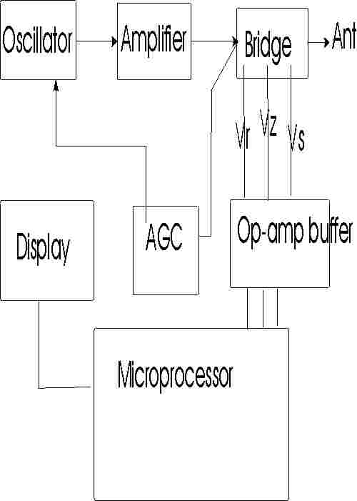
This is a rough outline of how this unit works:
The MFJ-259B, and other digitized MFJ antenna analyzers, compare three major voltages in a 50-ohm bridge circuit. They are:
All voltages are converted through an eight-bit A-D converter to a 256-bit digitized output with a test-display range of 0-255 bits. By knowing the ratio of these voltages, as compared to the AGC regulated RF source voltage, many different load parameters can be calculated.
An antenna analyzer could calculate everything (except sign of reactance) from measuring only Vs and Vz, but at certain impedances any small error in either Vs and Vz becomes critical. This is especially true when voltage is digitized into a 256-bit format (~0.4% steps). At certain impedances, an almost immeasurable voltage change will cause a sudden large jump in the measured impedance parameters.
When a load is reactive, the theoretical total of Vs and Vz exceeds 255 bits. Consequentially, if the 259's total Vz and Vs exceeds 255, the display indicates reactance. Although any calibration pot can affect readings, large reactance errors at impedance extremes commonly occur from improper setting of low-bit adjustments. Low-bit adjustments compensate diode linearity at low voltages. Â
To reduce display impedance jumping, SWR is weighed into the calculation of reactance and resistance at low SWR values. (An SWR bridge is most accurate when the load is closest to 50 ohms, which is a primary measurement area where impedance measurements through Vz and Vs become critical.) By factoring in a direct SWR measurement from an internal bridge, the analyzer can check and "correct" any small level errors in Vs or Vz. This reduces the impedance jump that would occur with a one-bit jump in voltage. This also why bits must be calibrated for near-perfect accuracy. A one-bit error can cause a resistive load to appear reactive (total of Vs and Vz must always be below 255 bits for a load to be considered resistive).
This calibration procedure is the correct procedure for later MFJ-259B's. Take any other information with a grain of salt. Since MFJ-259B firmware has several versions under the same model number, you may find some final performance or function verification steps invalid. These steps will involve parameters that do not appear on the display.
Before proceeding, be sure you have printed a copy of the board layout showing adjustment points, have read all this, and have suitable loads. Â
This unit has tracking and gain adjustments for Vz, Vs, and Vr. Detector system gain is set at high detector voltages or high-bits, by R53 (extreme SWR), R72 (Vz high load voltage bits), and R73 (Vs low load impedance, high-Vs series bits). Linearity is set at low voltages, by R90 (low load impedance), R88 (high load impedances), and R89 (low VSWR readings). Together, the low-bit and high-bit adjustments compensate diode linearity, making detector system output voltages closely track actual RF voltages appearing across bridge resistors.Â
| Control | Detector | Primary Load Calibration Function | determines |
| R73 | Vs high bits series load current | low load impedances, detector gain, high S bits | R and X low Z load |
| R90 | Vz low bit voltage across load | low load impedances, detector linearity, low Z bits | R and X Low Z load |
| R72 | Vz high bits voltage across load | high load impedances, detector gain, high Z bits | R and X High Z load |
| R88 | Vs low bits series load current | high load impedances, detector linearity, low S bits | R and X High Z load |
| R53 | Vr high SWR bits | high SWR readings, detector gain, high SWR bits | high SWR readings |
| R89 | Vr low SWR bits | low SWR readings and low reactances, SWR detector linearity | low SWR readings |
This unit also has meter calibration adjustments. The analog meters suffer from some scale-linearity problems, so they will be somewhat less accurate than the digital display in a perfectly calibrated unit. The metering adjustments, R56 (SWR) and R67 (Impedance), only affect analog meter readings. These meter adjustments do not affect the digital display, but digital detector adjustments will affect analog impedance meter readings.
Quiescent current (bias) in the RF amplifier section is adjustable. This adjustment directly affects output signal harmonic content. Harmonics are worse with low supply voltages, and with low impedance loads. Be sure you check the harmonics as outlined below, with a 1/4 wl open-circuit stub!!
Excessive harmonics can cause severe errors in measurement of frequency-selective loads, even when dummy-load SWR tests appear perfect. Loads most sensitive to harmonic-induced errors include, but are not limited to, antenna tuners, tank circuits, very short resonant antennas, and distance to fault and stub length measurements. If you notice something "funny" going on with a stub measurement, it may be a fault of incorrect bias.Â
Warning: Never calibrate around a sudden "problem" that appears. If a detector suddenly shifts voltage, the problem is almost certainly a defective detector diode. If the meter is recalibrated with a defective (leaky) diode, the meter will probably NOT track correctly with frequency. |
Tools and
Equipment:
#2 and #1 Phillips-head screwdrivers
Digital meter or accurate analog meter for checking supply voltage
Small set of non-metallic alignment wands for coils, and small jeweler's screwdrivers for controlsÂ
Well-filtered stable power supply, adjustable to 12-volts, or as specified
General-coverage receiver with level meter, or a spectrum analyzer
For stub testing and adjustments, a ~10 MHz 1/4wl open-stub. 15â of good-quality solid-dielectric RG-8, with a UHF connector at on end, open on the other end, will work.
2.2-ohm 1/4 or 1/2 watt film resistor Â
Accurate load set to include:
A.    Short
B.    12.5-W load
C.   50-W load
D.   75-W load
E.    100-W load
F.    200-W load
Call of Duty 2 runs on a heavily modified version of the Id Tech 3 engine (the same engine powering Quake III Arena). Wallhacks exploit the way this engine handles depth buffers and entity culling. Normally, the game engine improves performance by not drawing enemy players when they are behind cover. A wallhack disables this occlusion culling or changes the transparency of textures, leaving player models visible as outlines, boxes, or bright silhouettes even when they are out of line of sight.
Despite the lack of official rankings or esports prize money, cheating persists in Call of Duty 2. Psychological research suggests several motives:
What cheaters often fail to realize is that a wallhack/aimbot permanently ruins the game for themselves. Once you know where every enemy is at all times, the tension, surprise, and tactical depth vanish.
The development of a "Call of Duty 2 Wallhack Aimbot" feature involves complex technical challenges and significant ethical considerations. While this draft outlines potential features and functionalities from a purely technical standpoint, it's essential to approach such projects with an understanding of and respect for legal and ethical boundaries. This document is for educational purposes, encouraging responsible and informed decision-making in software development.
The story of cheating in Call of Duty 2 (2005) is a tale of the "Wild West" era of PC gaming, where the lack of sophisticated anti-cheat systems turned multiplayer lobbies into legendary battlegrounds between legit players and "hackers." The Rise of the "Script Kiddie"
In 2005, Call of Duty 2 was the gold standard for World War II shooters. However, unlike todayâs live-service games with kernel-level protection like Ricochet, CoD2 relied largely on PunkBuster
, a third-party anti-cheat that was often mocked for being a "joke" and easily bypassed by determined developers. Cheating typically manifested in two forms:
: These programs forcibly snapped the player's crosshairs onto an opponent's head. In a game like CoD2, where rifles like the Kar98k were one-shot kills, an aimbotter could wipe an entire 32-player server in seconds.
: These allowed players to see enemy character models through solid geometry, often rendered as bright "chams" (colored silhouettes) or boxes. This was particularly devastating on iconic maps like
, where knowing an enemy was behind a brick wall allowed for "pre-firing" or "wall-banging." The "Rage" vs. "Closet" Era The community quickly identified two types of cheaters: Rage Hackers
: These players didn't care about getting banned. They would spin in circles (spinbots), killing everyone instantly while taunting the lobby. Closet Cheaters
: These were more insidious. They used subtle wallhacks to gain information without making it obvious they were cheating, often trying to pass themselves off as "pro" players. This created a culture of deep suspicion where every lucky shot or good intuition was met with cries of "hacks!". Community Justice and Server Admins
Because official support for older CoD titles eventually waned, the responsibility for "policing" fell to the community. Private Servers
: Most serious players avoided the "Public" match-making and joined private servers with active human admins.
: The introduction of the killcam in early CoD games was the primary tool for verification. Players would record their screens to provide proof of "unnatural" snapping or tracking through walls to get someone banned from a specific clan's server. Screenshots
: Admins would use PunkBuster to force-trigger a screenshot of a suspected player's screen; if the screenshot showed the wallhack UI, they were instantly banned. The Legacy
The "arms race" between cheat providers and developers that started in games like CoD2 continues today. While modern games have more advanced detection, the core exploitsâwallhacking and aimbottingâremain the primary ways players seek an unfair advantage in the series. Today, many players look back with a mix of frustration and nostalgia for those early, chaotic days of WWII combat. Nostalgic memories of playing Call of Duty
Developing a paper on " Call of Duty 2 " wallhacks and aimbots typically involves exploring the technical architecture of game cheats, their impact on multiplayer ecosystems, or the cybersecurity measures used to combat them.
Below is an outline and key content for a technical research paper or analytical essay on this subject.
Paper Title: The Mechanics and Impact of Memory-Based Exploits in Call of Duty 2
Theme: Cybersecurity, Game Engine Architecture, and Digital Ethics. 1. Introduction
The Context: Call of Duty 2 (2005) utilized the IW 2.0 engine. Because it was released in an era of less sophisticated anti-cheat, it became a primary target for client-side modifications. Definitions:
Wallhack: A modification allowing players to see through solid objects by altering texture transparency or intercepting the rendering pipeline.
Aimbot: A script or software that automates player aiming by calculating the coordinates of enemy "bones" (hitboxes) and snapping the crosshair to them.
Thesis Statement: While cheats like wallhacks and aimbots provide an unfair competitive advantage by exploiting game memory, they also served as a catalyst for the evolution of modern anti-cheat technologies like PunkBuster and Valve Anti-Cheat (VAC). 2. Technical Mechanics of Cheat Software
Memory Injection and Hooking: Most COD2 cheats work by injecting a Dynamic Link Library (DLL) into the game process. This allows the cheat to read and write to the game's RAM. How Wallhacks Work (Chams vs. ESP):
Chams (Colored Models): Overriding the graphics driver (DirectX 9) to render player models with vibrant colors that ignore "depth testing," making them visible through walls.
ESP (Extra Sensory Perception): Drawing 2D boxes or text labels over enemy positions by reading the engine's entity list and converting 3D world coordinates into 2D screen coordinates. How Aimbots Work:
Vector Mathematics: The aimbot identifies the nearest enemy entity, calculates the pitch and yaw angles required to face that entity's head bone, and modifies the player's view angles in memory.
Silent Aim: A more advanced version that redirects bullets to the target without visibly moving the player's camera. 3. Impact on Gameplay and Community
Economic and Social Consequences: In competitive ladders (like the historical ClanBase), cheating undermined the integrity of the game, leading to the fragmentation of the community.
Psychological Elements: The "arms race" between cheaters and "clean" players often led to the rise of private, moderated servers with active human admins to supplement automated tools. 4. Countermeasures and Anti-Cheat Evolution
PunkBuster in COD2: Analysis of how PunkBuster attempted to scan for known cheat signatures and take "screen grabs" of a playerâs view to catch wallhackers.
Heuristic Detection: Modern anti-cheats look for "inhuman" mouse movements or impossible statistics, a direct response to the sophisticated aimbots developed for early shooters. 5. Conclusion
The legacy of Call of Duty 2 cheats is found in the robust security protocols of modern gaming. Understanding these early exploits is essential for cybersecurity professionals and game developers aiming to build fair, resilient digital environments.
In the dimly lit, cramped quarters of a small gaming arcade, a group of friends huddled around a sleek, high-performance gaming PC. Their eyes were glued to the screen as they dived into the intense, World War II-themed virtual battlefields of "Call of Duty 2." Among them was a young, enigmatic gamer known only by his handle, "ZeroCool."
ZeroCool was a legend in the gaming community, known for his unmatched skills in first-person shooters. However, tonight, he had brought with him something that would change the dynamics of their gaming session forever: a custom, highly sophisticated "wallhack aimbot."
The device, a product of meticulous engineering and coding by ZeroCool himself, promised an unfair advantage. It could see through walls, predict enemy movements, and automatically adjust aim to hit targets with uncanny accuracy. The group was both thrilled and intimidated by the prospect of witnessing its capabilities. call of duty 2 wallhack aimbot
As they entered the game, skepticism filled the air. "Is this thing for real?" one of them asked, eyeing the complex setup of wires and custom-built software interfaces ZeroCool had rigged up.
"One game, and you'll see," ZeroCool replied with a sly grin.
The match began, and at first, it seemed like any ordinary game. That was until ZeroCool started playing. The cursor on his screen darted with an unnatural fluidity, bullets seemingly always finding their mark, even when targets were obscured from view.
The group watched in awe as ZeroCool racked up kill after kill, his dominance on the virtual battlefield unmatched. However, their excitement quickly turned to dismay as they realized they were more or less along for the ride, their actions and efforts rendered moot by ZeroCool's overpowered tool.
The night wore on, with ZeroCool's reputation growing with each game. But as the session drew to a close, a sudden, unspoken question hung in the air: had ZeroCool gone too far? Was the integrity of the gameâand the fun they derived from itâbeing compromised by such a powerful cheat?
As they shut down the PC, the group began to discuss the implications. Some argued that it was just a tool, and like any tool, it was the intent and context of its use that defined it. Others believed it detracted from the skill and camaraderie they sought in gaming.
ZeroCool listened intently, his expression unreadable. When he finally spoke, his voice was low and contemplative. "I built this to push the limits," he said. "To see what's possible. But I also built it to remind myselfâand now youâthat there's a fine line between enhancing the experience and overshadowing it."
The group fell silent, each member lost in their thoughts. They knew that their gaming session had been forever changed by the demonstration of ZeroCool's creation. The night ended with an unspoken agreement: while the "wallhack aimbot" was an extraordinary piece of technology, it was also a reminder of the value of fair play and the joy derived from overcoming challenges without artificial advantages.
From that day on, ZeroCool's legend grew, not just as a master coder and gamer, but also as someone who, despite having the means to cheat, chose to compete with integrity, pushing the limits of what was possible within the rules of the game. The "wallhack aimbot" remained a secret, its existence a cautionary tale and a testament to the ethical boundaries of gaming innovation.
This paper explores the technical mechanics, ethical implications, and historical impact of "wallhacks" and "aimbots" within the context of Call of Duty 2
(CoD2). While these tools are primarily associated with unfair play, they represent a significant chapter in the evolution of game security and cybersecurity. Introduction
Released in 2005, Call of Duty 2 became a cornerstone of competitive first-person shooters (FPS). As the game's popularity grew, so did the development of third-party software designed to provide players with unnatural advantages. These tools, commonly known as "cheats" or "hacks," exploit the game's engine to bypass intended limitations. Technical Breakdown of Exploits Wallhacks (ESP - Extra Sensory Perception)
Mechanism: Wallhacks function by modifying the way the game engine renders textures or by intercepting the data sent from the server.
Implementation: In CoD2, this often involved "Chams" (Colored Models), which forced the engine to render player models in bright colors through solid surfaces. Alternatively, "driver-level" cheats would hook into the DirectX API to disable the depth-checking (Z-buffering) that normally hides objects behind walls. Aimbots
Mechanism: Aimbots are scripts or software that automate the aiming process.
Implementation: The software reads the memory of the game to find the exact 3D coordinates (
) of an enemy's "hitbox" (usually the head). It then forces the player's view-angle to snap to those coordinates instantly. In CoD2, advanced aimbots included "prediction" algorithms to account for bullet travel time and player movement. The Arms Race: Detection vs. Obfuscation
The prevalence of these tools led to a digital arms race. CoD2 utilized PunkBuster, an early anti-cheat system that performed memory scans and hardware ID (HWID) bans.
Hackers' Response: Developers created "undetectable" hacks that ran at the kernel level (Ring 0), hiding their presence from the anti-cheat software operating at the user level (Ring 3).
Community Response: Because software detection was imperfect, the CoD2 community relied heavily on "demo" reviewsârecordings of gameplay that administrators would manually inspect for "snappy" aim or "pre-firing" (shooting before a player is visible). Ethical and Social Impact
The use of wallhacks and aimbots fundamentally breaks the "magic circle"âthe shared agreement among players to follow the game's rules.
Competitive Integrity: In professional leagues like CAL or CyberEvolution, cheating scandals led to lifetime bans and the dissolution of entire teams.
Player Retention: Widespread cheating in public servers often leads to a "death spiral" where legitimate players leave, further concentrating the population of cheaters until the game becomes unplayable. Conclusion
The legacy of wallhacks and aimbots in Call of Duty 2 is a testament to the ongoing struggle between game developers and exploiters. While these tools damage the spirit of fair play, they have also driven significant advancements in software security and behavioral analysis within the gaming industry. Understanding these exploits is essential for modern developers aiming to build resilient, competitive environments.
The legacy of Call of Duty 2 (2005) is undeniable. As one of the definitive World War II shooters, it perfected the "iron sights" formula and remains a staple for nostalgic LAN parties and dedicated private servers. However, even decades later, the multiplayer landscape is still haunted by a controversial duo: Wallhacks and Aimbots.
While these tools are often sought out by players looking to dominate leaderboards, they come with significant risks to both your computer and your standing in the gaming community. Understanding the Hacks: Wallhacks vs. Aimbots
In the context of Call of Duty 2, "cheating" usually refers to external software that modifies how the game engine handles data. 1. Wallhacks (ESP)
A Wallhack (often part of an "ESP" or Extra Sensory Perception suite) allows a player to see through solid objects. In CoD2, this usually manifests as:
Chams: Changing the color of enemy player models (e.g., bright neon green) so they glow through walls.
Bounding Boxes: Drawing a box around opponents, making them visible across the entire map.
Name Tags: Revealing enemy names and health bars through terrain.
This gives a massive tactical advantage, allowing a player to "pre-fire" around corners or avoid ambushes in maps like Carentan or Toujane. 2. Aimbots
The Aimbot is more aggressive. It automatically snaps the player's crosshairs to an opponent's hitboxes (usually the head or chest). In a fast-paced game like CoD2, where the "Time to Kill" is very low, an aimbotter can clear a room in seconds without missing a single shot. Advanced aimbots often include "Silent Aim" or "Smoothing" to make the movements look more human and less robotic to spectators. The Risks of Using Hacks in CoD2
While it might be tempting to install a "Call of Duty 2 Multihack," the downsides far outweigh the temporary thrill of a high K/D ratio.
Malware and Viruses: Most "free" hacks found on obscure forums are disguised malware. Because these programs need to inject code into your game, they often require you to disable your antivirus, leaving your PC vulnerable to keyloggers and ransomware.
PB Bans (PunkBuster): Even though the game is old, many active servers still run PunkBuster. This anti-cheat software maintains a database of known "signatures." Once caught, your GUID (Global Unique Identifier) is blacklisted, banning you from almost all reputable servers globally.
Community Blacklisting: The CoD2 community is small and tight-knit. Server admins are experts at spotting "unnatural" gameplay. Once you are suspected of wallhacking, you will likely be banned from community Discord servers and private leagues, effectively ending your ability to play the game online. The Better Alternative: Improving Your Skill Call of Duty 2 runs on a heavily
The beauty of Call of Duty 2 lies in its simplicity and mechanical depth. Instead of risking a ban, players can improve through:
Map Knowledge: Learning common "pre-fire" spots and grenade tosses (nades) provides a "legal wallhack" by predicting exactly where enemies will be.
Sensitivity Tuning: Lowering your mouse sensitivity can provide the precision needed to rival an aimbotâs accuracy.
Sound Triangulation: Using a good headset to hear footsteps through walls is a legitimate way to track enemies. Conclusion
Searching for a Call of Duty 2 wallhack or aimbot might seem like a shortcut to fun, but it ultimately ruins the experience for everyone involvedâincluding the cheater. By relying on skill and map awareness, you preserve the integrity of a classic game that has survived for nearly twenty years.
Disclaimer: This article is for educational purposes only. We do not condone or provide links to cheating software, which violates the Terms of Service of the game and ruins the competitive experience for others.
The Impact of Cheating in Online Gaming: A Look at Call of Duty 2 Wallhacks and Aimbots
The world of online gaming has exploded in popularity over the past decade, with millions of players worldwide engaging in immersive and competitive experiences. One of the most iconic and enduring franchises in this space is Call of Duty, with its second iteration, Call of Duty 2, still boasting a dedicated player base. However, alongside the excitement and camaraderie of online gaming, a more unsavory phenomenon has emerged: cheating.
What are Wallhacks and Aimbots?
Two of the most common types of cheats employed in first-person shooters like Call of Duty 2 are wallhacks and aimbots.
The Appeal and the Consequences
The appeal of wallhacks and aimbots is clear: they offer a quick fix for players looking to dominate in competitive games without putting in the time and effort to hone their skills. However, the use of such cheats comes with severe consequences:
The Fight Against Cheating
The battle against cheating in online gaming is ongoing. Developers are continually updating their anti-cheat software, while also seeking to educate players about the risks and consequences of cheating. For Call of Duty 2 and other games, it's essential for the community to report suspicious activity and for players to understand the value of fair play.
Alternatives to Cheating
For players looking to improve their game without resorting to cheats, there are several constructive alternatives:
Conclusion
The allure of wallhacks and aimbots in Call of Duty 2 and similar games is understandable but misguided. While these cheats may offer short-term gains, they ultimately lead to a less enjoyable experience for all involved. By choosing fair play and focusing on skill development, players can achieve a more rewarding and sustainable experience in the world of online gaming.
Call of Duty 2 , hacks like typically function by injecting code into the game's executable or memory to bypass standard engine limitations. These modifications are strictly prohibited under the Call of Duty Security and Enforcement Policy , and using them in multiplayer can lead to permanent bans.
Below are the common features found in these types of third-party modifications: Wallhack Features
Wallhacks (often categorized under ESPâExtra Sensory Perception) allow players to see information through solid objects: Chams (Player Highlighting):
Renders enemy models in bright, solid colours (like red or neon green) that remain visible through walls. Name Tags:
Displays the names of enemies above their heads, even when they are obscured. Health Bars: Shows real-time health data for opponents. Distance ESP: Indicates exactly how far away an enemy is. Weapon ESP: Shows what weapon an enemy is currently holding. Bounding Boxes:
Draws a square or 3D box around enemy players to highlight their exact position. Aimbot Features
Aimbots provide automated targeting assistance to ensure near-perfect accuracy:
Automatically snaps the player's crosshair to the nearest enemy's head or torso when a hotkey is pressed. Auto-Fire (Triggerbot):
Automatically fires the weapon the instant an enemy enters the crosshair. Smooth Aim:
Mimics human movement by slowing down the snap-to-target speed to make the cheat harder for anti-cheat software or other players to detect. FOV (Field of View) Settings:
Allows the user to restrict the aimbot to a specific area of the screen so it doesn't "snap" to enemies behind the player. No Recoil/No Sway:
Removes weapon kick and idle sway, ensuring bullets go exactly where the crosshair is pointed. Internal Console Cheats (Single Player Only)
For the single-player campaign, you can enable "official" cheats through the game's developer console without using risky third-party software: Apple Support Community Enable Console: Options > Game Options Enable Console Activate Developer Mode: key and type seta developer 1 Standard Codes: for invincibility, for all weapons, or to fly through walls. Apple Support Community Modern anti-cheat systems like
actively monitor for unauthorized software and can detect these modifications in multiplayer environments. Call of Duty enabling specific console commands for the campaign, or do you need information on anti-cheat protections
Call of Duty Security and Enforcement Policy - Activision Support 23 Jan 2026 â
Call of Duty 2: A Brief Overview
Call of Duty 2 is a first-person shooter video game developed by Infinity Ward and published by Activision. Released in 2005, it's the second installment in the Call of Duty series. The game is set during World War II and features various multiplayer modes.
Wallhacks and Aimbots: Understanding the Concepts
In the context of first-person shooter games like Call of Duty 2, a wallhack refers to a type of cheat or hack that allows players to see through walls and other solid objects, giving them an unfair advantage in gameplay. This can be particularly useful in multiplayer modes, where players can use this ability to detect and engage enemies who are hiding or camping. What cheaters often fail to realize is that
An aimbot, on the other hand, is a type of cheat that automates the process of aiming at enemies. Aimbots can use various algorithms to track and predict enemy movements, allowing players to quickly and accurately target and eliminate opponents.
Using Wallhacks and Aimbots in Call of Duty 2
While it's technically possible to create or obtain wallhacks and aimbots for Call of Duty 2, using these cheats can have significant consequences. Here are some key points to consider:
Alternatives to Cheating
If you're looking to improve your gameplay in Call of Duty 2, there are many legitimate ways to do so. Here are a few suggestions:
By focusing on legitimate gameplay and improvement strategies, you can enhance your gaming experience and enjoy the game without resorting to cheats or hacks.
In the decades since its 2005 release, Call of Duty 2 (CoD2) has remained a cornerstone of retro competitive shooters. However, its longevity has been shadowed by the persistent use of third-party softwareâspecifically wallhacks and aimbotsâthat bypasses the gameâs original security to provide unfair advantages. These tools exploit the game's aged architecture, creating a divide between those seeking nostalgic fair play and those utilizing modern exploits. Technical Breakdown: How Cheats Work in CoD2
Cheating software for legacy titles like Call of Duty 2 typically functions by interacting with the game's executable (EXE) or dynamic link libraries (DLLs).
Aimbots: These are scripts designed to automate the aiming and shooting process.
Memory Injection: Most aimbots for CoD2 work by reading the computerâs memory to locate enemy player coordinates.
Precision and Smoothing: While some "rage hacks" snap instantly to heads, more sophisticated versions use "smoothing factors" to mimic human mouse movement, making them harder to detect by spectators.
Wallhacks (ESP): Also known as "Extrasensory Perception," these tools reveal hidden information.
Texture Manipulation: Some versions modify game textures to make walls transparent.
Overlays: Modern wallhacks often draw boxes (bounding boxes) or skeletal frames over enemy models, allowing a player to see their position and health through solid geometry. The Impact on the Community
The presence of wallhacks and aimbots in Call of Duty 2 has significant consequences for its remaining player base: RICOCHET Anti-Cheat: Call of Duty's Anti-Cheat Initiative
The screen glowed with a sickly green hue, the "wallhack" turning the solid brick ruins of El Alamein into translucent glass. To Elias, the world of Call of Duty 2
wasn't a battlefield; it was a shooting gallery where the targets were outlined in bright, neon red through three feet of concrete.
He adjusted his headset, the static of the 2005-era voice chat crackling in his ears. On the other side of the map, a squad of Allied players was planning a strategic push toward the flak 88s. They moved with caution, popping smoke and checking corners, playing the game as it was meant to be played. tapped a key, and the "aimbot" hummed into life.
His Kar98k didn't just fire; it snapped. The crosshair jumped with mechanical, inhuman precision. A headshot through a wooden crate.
Another through a stone wall. The killfeed scrolled relentlessly: [WH]Specter â> Headshot â> Sgt_Miller.
"Cheater!" the chat exploded. "Report this guy! How is he hitting those?"
smirked, leaning back in his creaky office chair. For him, the thrill wasn't in the skill; it was in the god-like power of knowing exactly where everyone was. He watched the red outlines scramble in confusion, spinning in circles as they tried to find the sniper who could see through the very earth. But then, the screen flickered.
His character froze mid-reload. The translucent walls turned solid again, then pitch black. A single line of white text appeared in the center of his monitor, replacing the chaotic battlefield:
"Global Ban Issued: Hardware ID Recognized. The hunt is over." The hum of the server died.
sat in the sudden silence of his room, the neon red outlines fading from his vision, leaving him alone in the dark with nothing but a blank screen and a game he no longer knew how to play.
The legacy of Call of Duty 2 (CoD2) is inextricably linked to the early "arms race" between elite competitive players and cheat developers. While Modern Warfare titles now use kernel-level systems like
, the era of CoD2 relied on community-driven enforcement and the now-classic PunkBuster anti-cheat. The Mechanics of "Old School" Cheating
In CoD2, cheats typically functioned by injecting code into the gameâs memory or modifying its DLL files to extract hidden data.
: These tools read enemy coordinates from the game's memory to calculate a directional vector. The script then overrides the player's view angles (pitch and yaw) to snap the crosshair onto a target, often aiming for the head. Modern variations include "humanized" aimbots that add smoothing to avoid detection. Wallhacks (ESP)
: Also known as "Extra Sensory Perception," these hacks render player skeletons or silhouettes through solid objects. In CoD2, this was often achieved by bypassing the game's rendering instructions to make walls transparent or highlight player models regardless of visibility. Cvar Exploits
: Sophisticated players sometimes used "cvar" (console variable) exploits, such as r_intensity
, to gain visual advantages by altering how light and textures were rendered, which server admins tracked via tools like The Defensive Era: PunkBuster and PBBans
Because CoD2 lacked modern centralized matchmaking, security was managed at the server level. PunkBuster
: A self-updating software by Even Balance Inc. that scanned for known cheat signatures and took periodic screenshots of a player's view (PBSS) to catch wallhackers. PBBans Master Ban Index (MBI)
: This community-run hub pooled information from thousands of private servers. Once a player was caught on one "streaming" server, their unique identifier was added to a global blacklist, effectively banning them from all participating CoD2 servers. Competitive Impact and Culture
In the ultra-competitive PC scene of the mid-2000s, cheating was a significant source of drama. The difficulty of distinguishing between "god-tier" aim and a subtle aimbot led to intense scrutiny of "demos" (recorded gameplay files). About Us - PBBans
While no one has been prosecuted for cheating in Call of Duty 2, cheat developers for modern titles (e.g., Call of Duty: Warzone) have faced lawsuits from Activision, resulting in million-dollar settlements.
Use a forum-based registration system. New players must play 10 hours under observation before gaining full server access.
| Note 2: The power source should be the LOWEST expected operating voltage. DO NOT use a standard "wall-wart" or batteries! You can reduce voltage from a conventional 13.8v regulated supply by adding a few series diodes. Silicon diodes will normally drop about 0.6volts or so per diode. Three or four series diodes will reduce voltage below 12 volts. |
|
WARNING: The MFJ-1315 AC adapter or other "wall-warts" should NOT be used to power the unit for most alignment steps. It is best to calibrate at typical lower expected battery voltage. |
Visual Inspection: Before, during, and after calibration, be mindful of physical condition. Watch for missing or loose hardware. Do not tug, stress, or repeatedly flex leads, or carelessly flop or toss things about. Unlike my bench, keep your workbench clean. Follow these rules the entire time you have the unit apart!
Battery
Tray Removal: This step provides access to trim-pots and most inductor
adjustments.
[Â ] Remove last two batteries at each end of the tray.
[Â ] Remove two battery holder screws (right side) and extract the tray.
[Â ] Always position the battery tray to minimize strain on wires.Â
[Â ] Do not reinstall batteries. If the holder or leads get shorted, you can melt things.
Refer to the board layout below for specific adjustment locations.
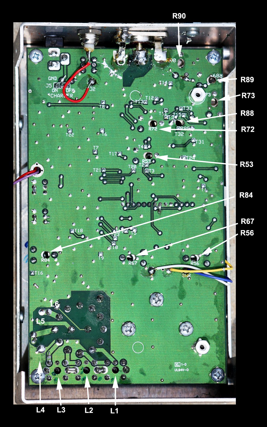
R90 Load Z low-bit
R89 swR low bits
R73 Series high bits
R88 Series low bits
R72 Load Z high bits
R53 swR high bits
R84 Amplifier bias null harmonic
R67 SWR meter
R56 Impedance meter
L1 Lowest range
L6 Highest range
Figure 1
Step 3, verify VFO range
Band Overlapping: Each band should overlap the next by a small amount to ensure gap-free coverage from 1.8 MHz to 170 MHz. While viewing the LCD Frequency Display, wiggle the bandswitch from side-to-side gently. Watch for any display or meter dropout. Starting from the highest frequency band, check each band as follows:
114-170 MHz: L6 oscillator squeeze-spread tunes from below 114.0 MHz to above 170.0 MHz. Check tune for dead spots.
70-114 MHz: L5 oscillator squeeze-spread tunes from below 70.0 MHz to above 114.0 MHz
27-70 MHz: slug oscillator tunes from below 27.0 MHz to above 70.0 MHz.
10-27 MHz: slug oscillator tunes from below 10.0 MHz to above 27.0 MHz.
4-10 MHz: slug oscillator tunes from below 4.0 MHz to above 10.0 MHz.
1.8-4 MHz: slug oscillator tunes from below 1.8 MHz to above 4.0 MHz. Check tune for dead spots.
While verifying band overlap, check the lowest and highest bands carefully for dead spots. The LCD Display will indicate 000.000MHz if a dead spot occurs. Dead spots generally indicate a defective tuning capacitor (TUNE).Â
If wiggling bandswitch causes a dropout, the switch may have dry or dirty contacts. Less likely are poor solder joints, but check solder joints first. If you must clean and lubricate the switch, be aware it is a difficult task. The entire board needs to be lifted from the case front. Dirty band-switch contacts may be restored with spray tuner-cleaners, or WD-40. The best place to spray the switch is from the front side (shaft side), right below the nut. You must remove the switch indexing tab retainer nut and the metal switch retainer (stop) under the nut. Be sure the stop goes back exactly as removed.
To correct overlap problems, locate and retune the appropriate VFO coil (see pictorial for coil locations). Note that L1-L4 are slug-tuned and require an insulated hex-head tuning wand. Using the wrong size or worn tuning tool may stress and crack a tuning slug.Â
Inductors L5 and L6 are located on the component side of the board and are compression-tuned (press turns closer together to lower frequency or spread apart to raise frequency). Make only very small corrections--especially to L5 or L6--and recheck the band you are adjusting. You should also check the next lower band after each adjustment to ensure that the lower band hasn't moved excessively.
| Important Warning: VFO coils MUST be aligned from highest frequency band to the lowest frequency band. All higher ranges affect lower bands, with the adjacent higher band having the largest effect. Do not attempt VFO coil adjustment unless you are experienced working with VHF-LC circuitry or analog tuned circuit alignment procedures. |
Harmonic Suppression/ generator bias level: Connect the analyzer exactly as shown below.Â
WARNING:Â
Incorrect
adjustment of R84Â will NOT show with resistive dummy loads!!! The unit will appear to calibrate correctly, but will
produce errors in stub length, distance-to-fault, and other frequency-selective
or resonance functions.
When R84 is set properly, harmonic suppression of â30dBc or more should be possible across most of the analyzerâs tuning range.
This particular adjustment should be made at the lowest expected operating voltage. Proper alignment requires a 12.0-volt regulated supply as a power source. NEVER use an AC adapter, or any supply voltage higher than 12-volts, when making this adjustment.Â
A calibrated spectrum analyzer works best for monitoring harmonic
output, but a well-shielded general-coverage receiver with signal-level meter
will also work. The receiver MUST
be "T'd" into the analyzer just as the spectrum analyzer is, the "T"
and resistor must be located right at the analyzer ANT connector. If
you do not have a good-quality receiver or spectrum analyzer, you
probably should not make this adjustment. If you insist on adjusting bias
without a receiver or analyzer, you can connect a 1/4 wave open stub, tune to
the null in Vz, and watch test-mode Vz while adjusting R89. Vz will roughly indicate
total even harmonic voltage, when the analyzer is set at the stub's exact resonant
frequency. Entering the test mode is described in Detector Calibration (Step
6).   Â
[Â ] a. Install either a 15â RG-8 open stub, or a low impedance load resistor and spectrum measurement device, and tune the analyzer to approximately 10-15 MHz or exactly to stub resonance.Â
[Â ] b. (stub and internal Vz use only) Observing Vz on the data display (analyzer test mode), adjust frequency until the lowest fundamental output reading (or lowest impedance) is obtained. You should clearly see the MFJ analyzer's fundamental frequency output voltage (Vz) go through a deep null.Â
[Â ] c. Observe the analyzer frequency reading. This is the approximate resonant frequency of the stub.Â
[Â ] d. Without changing the analyzer test frequency setting, observe the second harmonic level. This harmonic will be at twice the MFJ analyzer frequency counter reading. Alternatively, you can watch Vz on the test mode display.
[ ] e. Adjust R84 for lowest 2nd harmonic meter reading on the receiver, lowest Vz test-mode reading, or lowest harmonic levels on the spectrum analyzer. Be SURE the fundamental frequency level remains nulled in the stub, if a stub is used.Â
This critical sequence calibrates A-D conversion for various load conditions. If you know your unit has been tampered with, preset trim pots R88, R89, and R90 to their center positions before continuing. If any control bottoms-out during adjustment procedures, you either installed an incorrect load for the control adjustment or the analyzer has a defective detector diode. Â
To prepare for detector tracking alignment, place the analyzer in Test Mode. Entering test mode may be tricky with some units, and it may take practice. To enter Test Mode:
[Â ] Turn power off.
[Â ] Hold down MODE and GATEÂ buttons while restoring power.
[Â ] As display comes up, slowly (about 1 second period) rock between applying finger-pressure on the MODE and GATE switches. The best method is to use two fingers, rocking your hand from side-to-side to alternate your fingers between the two buttons.
[Â ] Confirm analyzer has entered test mode (it may take more than one try).
[Â ] Using the MODE button, advance display to the R-S-Z screen (shown below).
Â
![]()
![]()
![]() 10.000
MHz
10.000
MHz
For initial adjustments, if the unit has never been aligned, start here. Otherwise, skip down to the next break.
![]() Â
Â
Â
Â
[Â ] Tune
analyzer operating frequency to approximately 10-15
MHz. This is not critical.
[Â ] Leave antenna connector Open
[Â ] Set R72 for Z=255
[Â ] Set R88 for S=000, if possible
[Â ] Install the Short
[Â ] Set R90 for Z=000, if possible
[Â ] Set R73 for S=255
[Â ] Set R53 for R=255
The list below is the start for any second or third run-through points, or calibration touch ups. You have now set initial rough settings for all three detectors, proceeding to impedance calibration loads
[Â ] Install 12.5-W load
[Â ] Set R90 for Z=051
[Â ] Set R73 for S=204
[Â ] Set R53 for R=153 (for 4:1 digital SWR)
Change Load to continue impedance calibration
[Â ] Install 200-W load
[Â ] Set R88 for S=051
[Â ] Set R72 for Z=204
Change Load to continue impedance calibration
[Â ] Install 12.5-W load
[Â ] Reset R90 for Z=051
[Â ] Reset R73 for S=204
[Â ] Reset R53 for R=153 (4:1 digital SWR)
Change Load to continue impedance calibration
[Â ] Install 200-W load
[Â ] Verify or reset R88 for S=051
[Â ] Verify or set R72 for Z=204
[Â ]Â Verify or set R53 for near R=153 (4:1 digital SWR). This reading should be compromised with the 12.5 ohm load.
Change Loads to calibrate SWR
[Â ] Install 75-W load
[Â ] Set R89 for R=051 (digital 1.5:1 SWR)
[Â ] Set R56 for SWR Meter 1.5:1
Change Loads to calibrate impedance meter
[Â ] Install 50 ohm load
[Â ] Set R67 for an Impedance Meter reading of 50-ohms
You have now set impedance tracking at 12.5 and 200 ohms, digital SWR tracking between 1.5:1 and 4:1 SWR, and set the SWR analog meter for 1.5:1 SWR point. There is not any analog SWR meter tracking adjustment, so you may want to compromise R56 with several SWR test loads. R56 will not affect anything except the analog SWR meter reading.
After verifying calibration with all loads, carefully reassemble your antenna analyzer.
Periodic VerificationÂ
Periodically check your analyzer with test load!
| Â | |
| Â |  |
 Â
12.5W = (4) 50-ohm or a single 15W and 82W 1% in parallel
                                   50W = 49.9-ohm or 100W and 100W in parallel
                                   75W = 75-ohm or 150W and 150W in parallel
                                   100W = 100W
                                   200W = 200-ohm or 100W + 100W in series
I use male BNC connectors with the locking sleeve removed, with surface mount resistors. These connectors will plug into type-N 50-ohm connectors as "quick connect" connectors:
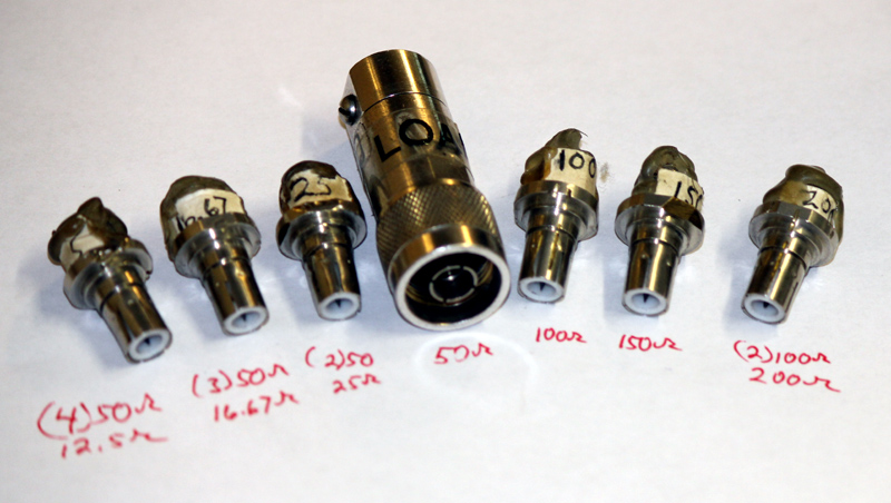
 Important Note: Many simple HF loads, inside PL259 connectors, will not be accurate above 30 MHz. Only precision terminations should be used in the VHF region. Even then, there can be some errors from connector and trace lengths inside the analyzer. The MFJ-259B does not correct for connector impedance bumps, or correct for the electrical length between an external load and the detectors inside the unit.
©2003-2012 W8JI